
# Dead Wheels
WARNING
If you are not using dead wheels, skip this section.
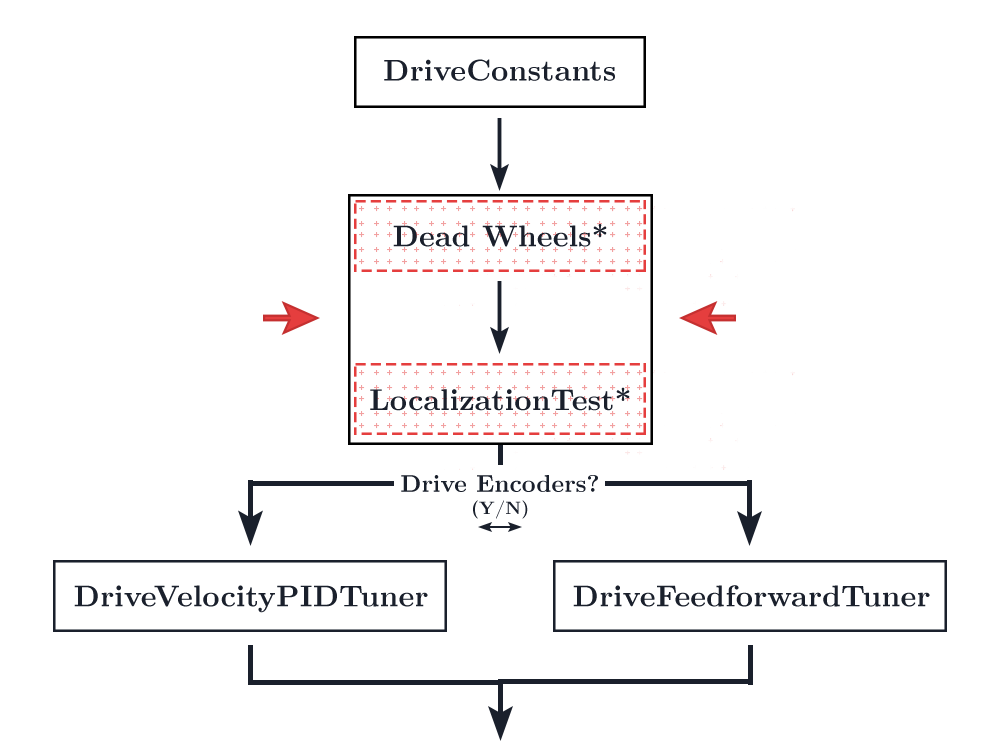
Your configuration will depend on whether you have two or three dead wheels. Don't know the difference? Check the FAQ.
If you're using a two-wheel setup, read only the two-wheel odometry section.
If you're using a three-wheel setup, read only the three-wheel odometry section.
# Two-Wheel Odometry
If you opt for the two wheel configuration, you will be using a gyroscope of your choice as the source for your heading. By default, you will be using the REV Hub's internal BNO055 gyroscope.
Feel free to use your own gyroscope. Simply declare it in SampleMecanumDrive.java and override the getRawExternalHeading() function.
Download this file (opens new window) and stick it in your TeamCode folder, preferably next to the StandardTrackingWheelLocalizer.java file just for organizational purposes.
Open the TwoWheelTrackingLocalizer.java file (that you just downloaded) to edit.
# Ticks Per Rev/Wheel Radius/Gear Ratio
/* Lines 37-39 in TwoWheelTrackingLocalizer.java */
public static double TICKS_PER_REV = 0;
public static double WHEEL_RADIUS = 2; // in
public static double GEAR_RATIO = 1; // output (wheel) speed / input (encoder) speed
TICKS_PER_REV is the number of "ticks" the encoders will count per revolution. You will find the specs of your encoders on your manufacturer's site. Be sure to find the Counts Per Revolution or CPR. The REV Through Bore Encoder has a TICKS_PER_REV of 8192.
WHEEL_RADIUS is the radius of the dead wheel. Make sure this is the radius, not diameter.
GEAR_RATIO is the ratio of the output (wheel) speed to input (encoder) speed. If you are not gearing your encoders, leave this at 1.
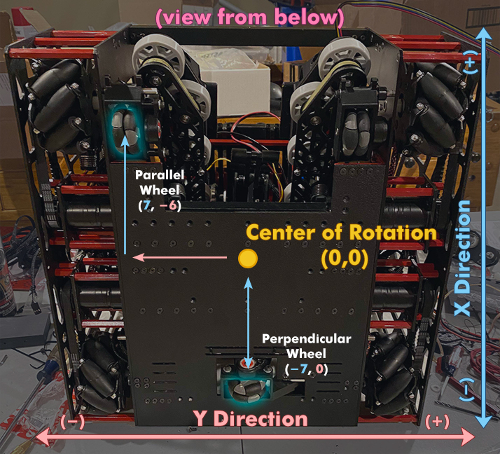
# Parallel/Perpendicular X/Y
/* Lines 41-45 in TwoWheelTrackingLocalizer.java */
public static double PARALLEL_X = 0; // X is the forward and back direction
public static double PARALLEL_Y = 0; // Y is the strafe direction

public static double PERPENDICULAR_X = 0; // X is the forward and back direction
public static double PERPENDICULAR_Y = 0; // Y is the strafe direction
Put in the X/Y coordinates of your perpendicular and parallel wheels. Remember that the X axis is the forward/back direction and the Y axis is the left/right direction. This is fairly standard for robotics/aviation/etc.
# Encoder Directions
Make sure to reverse the encoder directions when appropriate.
E.g.
/* Lines 60-63~ in TwoWheelTrackingLocalizer.java */
parallelEncoder = new Encoder(hardwareMap.get(DcMotorEx.class, "parallelEncoder"));
perpendicularEncoder = new Encoder(hardwareMap.get(DcMotorEx.class, "perpendicularEncoder"));

// TODO: reverse any encoders using Encoder.setDirection(Encoder.Direction.REVERSE)

// If you need to reverse the perpendicular encoder:
// Vice-versa for the other encoder
perpendicularEncoder.setDirection(Encoder.Direction.REVERSE);
WARNING
If you are using the Rev Through Bore encoders, please read the following section
If your encoder velocity exceeds 32767 counts per second, it will cause an integer overflow when calling getVelocity(). This is because the Rev Hub firmware sends the velocity data using 16 bit signed integers rather than 32 bit. Due to the Rev Through Bore encoders' absurdly high CPR, this happens at around 4 rounds per second. Or only 25 inches per second with 2 inch diameter wheels.
Change the getRawVelocity() functions to getCorrectedVelocity() in the getWheelVelocities() function to fix this integer overflow:
/* Lines 86-95 in TwoWheelLocalizer.java */
public List<Double> getWheelVelocities() {
    // TODO: If your encoder velocity can exceed 32767 counts / second (such as the REV Through Bore and other
    //  competing magnetic encoders), change Encoder.getRawVelocity() to Encoder.getCorrectedVelocity() to enable a
    //  compensation method

    return Arrays.asList(
            encoderTicksToInches(parallelEncoder.getCorrectedVelocity()),
            encoderTicksToInches(perpendicularEncoder.getCorrectedVelocity())
    );
}
# Hardware ID's
/* Lines 60-61 in TwoWheelTrackingLocalizer.java */
parallelEncoder = new Encoder(hardwareMap.get(DcMotorEx.class, "parallelEncoder"));
perpendicularEncoder = new Encoder(hardwareMap.get(DcMotorEx.class, "perpendicularEncoder"));
Ensure that these ID's match up with your Rev Hub config ID's.
# IMU
/* Lines 134-137 in SampleMecanumDrive.java */
imu = hardwareMap.get(BNO055IMU.class, "imu");
BNO055IMU.Parameters parameters = new BNO055IMU.Parameters();
parameters.angleUnit = BNO055IMU.AngleUnit.RADIANS;
imu.initialize(parameters);
Ensure that the IMU is initialitzed in the SampleMecanumDrive.java class. You shouldn't need to change anything if you downloaded the quickstart and are using the Rev Hub IMU. This section should be changed if you are using your own external gyro.
# IMU Velocity Axis
In your SampleMecanumDrive.java file, scroll to the very bottom to find the getExternalHeadingVelocity function. Ensure that the function returns the axis that your IMU rotates about for your configuration. Consult the ASCII diagram provided in the file for a visual on which axis you should choose. If your REV Hub is mounted flat, the bot will rotate about the Z axis. If it is on its side with the motor ports facing up or down, the robot will rotate about the Y axis. If the servo ports are facing up or down, the bot will rotate about the x axis.
/* About lines 399-419 in SampleMecanumDrive.java */
@Override
public Double getExternalHeadingVelocity() {
    // TODO: This must be changed to match your configuration
    //                           | Z axis
    //                           |
    //     (Motor Port Side)     |   / X axis
    //                       ____|__/____
    //          Y axis     / *   | /    /|   (IO Side)
    //          _________ /______|/    //      I2C
    //                   /___________ //     Digital
    //                  |____________|/      Analog
    //
    //                 (Servo Port Side)
    //
    // The positive x axis points toward the USB port(s)
    //
    // Adjust the axis rotation rate as necessary
    // Rotate about the z axis is the default assuming your REV Hub/Control Hub is laying
    // flat on a surface

    return (double) imu.getAngularVelocity().zRotationRate;
}
# Set Localizer in SampleMecanumDrive
After you've configured your localizer, go back to the SampleMecanumDrive.java file.
Look at about line 168. You should find a comment stating "// TODO: if desired, use setLocalizer() to change the localization method"
Under this comment, add the following line:
/* About line 168 in SampleMecanumDrive.java */

// TODO: if desired, use setLocalizer() to change the localization method
// for instance, setLocalizer(new ThreeTrackingWheelLocalizer(...));

setLocalizer(new TwoWheelTrackingLocalizer(hardwareMap, this));
You have set the localizer!
# Three-Wheel Odometry
If you opt for the three wheel configuration, you will be using the two parallel wheels as the source for your heading.
Open up the StandardTrackingWheelLocalizer.java file.
# Ticks Per Rev/Wheel Radius/Gear Ratio
/* Lines 30-32 in StandardTrackingWheelLocalizer.java */
public static double TICKS_PER_REV = 0;
public static double WHEEL_RADIUS = 2; // in
public static double GEAR_RATIO = 1; // output (wheel) speed / input (encoder) speed
TICKS_PER_REV is the number of "ticks" the encoders will count per revolution. You will find the specs of your encoders on your manufacturer's site. Be sure to find the Counts Per Revolution or CPR. The REV Through Bore Encoder has a TICKS_PER_REV of 8192.
WHEEL_RADIUS is the radius of the dead wheel. Make sure this is the radius, not diameter.
GEAR_RATIO is the ratio of the output (wheel) speed to input (encoder) speed. If you are not gearing your encoders, leave this at 1.
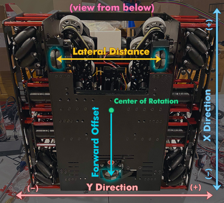
# Lateral Distance/Forward Offset
/* Lines 34-35 in StandardTrackingWheelLocalizer.java */
public static double LATERAL_DISTANCE = 10; // in; distance between the left and right wheels
public static double FORWARD_OFFSET = 4; // in; offset of the lateral wheel
LATERAL_DISTANCE is the distance from the left and right wheels.
FORWARD_OFFSET is the distance from the center of rotation to the middle wheel. The FORWARD_OFFSET is positive when in front of the wheels and negative when behind the wheels (closer to the back).
# Encoder Directions
Make sure to reverse the encoder directions when appropriate.
E.g.
/* Lines 46-63~ in StandardTrackingWheelLocalizer.java */
leftEncoder = new Encoder(hardwareMap.get(DcMotorEx.class, "leftEncoder"));
rightEncoder = new Encoder(hardwareMap.get(DcMotorEx.class, "rightEncoder"));
frontEncoder = new Encoder(hardwareMap.get(DcMotorEx.class, "frontEncoder"));

// TODO: reverse any encoders using Encoder.setDirection(Encoder.Direction.REVERSE)

// If you need to reverse the middle encoder:
// Vice-versa for the other encoders
frontEncoder.setDirection(Encoder.Direction.REVERSE);
# Set Localizer in SampleMecanumDrive
After you've configured your localizer, go back to the SampleMecanumDrive.java file.
Look at about line 131. You should find a comment stating "// TODO: if desired, use setLocalizer() to change the localization method"
Under this comment, add the following line:
/* About line 131 in SampleMecanumDrive.java */

// TODO: if desired, use setLocalizer() to change the localization method
// for instance, setLocalizer(new ThreeTrackingWheelLocalizer(...));

setLocalizer(new StandardTrackingWheelLocalizer(hardwareMap));
You have set the localizer!
# Deleting the IMU
The IMU does not serve a purpose in three wheel odometry. Thus, it would be ideal to get rid of the default initialization in SampleMecanumDrive. IMU initialization can add 2-3 seconds to the opmode initialization and it's quite annoying.
Open SampleMecanumDrive.java and delete this entire section:
/* Lines 134-137 in SampleMecanumDrive.java */

// TODO: adjust the names of the following hardware devices to match your configuration
imu = hardwareMap.get(BNO055IMU.class, "imu");
BNO055IMU.Parameters parameters = new BNO055IMU.Parameters();
parameters.angleUnit = BNO055IMU.AngleUnit.RADIANS;
imu.initialize(parameters);
Just for safety reasons, replace the returns of getRawExternalHeading() and getExternalHeadingVelocity() with zero:
/* Lines 393-396 in SampleMecanumDrive.java */
@Override
public double getRawExternalHeading() {
    return 0;
}

@Override
public Double getExternalHeadingVelocity() {
    return 0.0;
}
# Tuning - Two-Wheel
Tuning your dead wheels is one of the most important steps along the entire tuning process. This is not constrained to Road Runner. Any time you choose to use dead wheels, whether it be in Road Runner, FTCLib, or your own home brew path following, your localization should be as accurate as possible.
# Adjusting the wheel radius
TIP
This isn't quite necessary for everyone. You may choose to skip over this section. However, I did find that this process would increase localization accuracy by an additional 1% or so. 1% may not sound like much but over 100 inches that is an entire inch. During the FTC Skystone (2019-2020) season, a 4-5 stone autonomous programmed traveled well over 100 inches and an entire inch of extra accuracy may have made a big difference.
- First, open up the
TwoWheelTrackingLocalizer.java - Declare two variables,
X_MULTIPLIERandY_MULTIPLIER, in your class:
/* Lines 46-47 in TwoWheelTrackingLocalizer.java */
public static double X_MULTIPLIER = 1; // Multiplier in the X direction
public static double Y_MULTIPLIER = 1; // Multiplier in the Y direction
A finished example of where these go may be found here (opens new window).
- Add these mulitpliers to the
getWheelPositions()andgetWheelVelocities()functions like so:
/* Lines 77-97 in TwoWheelTrackingLocalizer.java */
@NonNull
@Override
public List<Double> getWheelPositions() {
    return Arrays.asList(
            encoderTicksToInches(parallelEncoder.getCurrentPosition()) * X_MULTIPLIER,
            encoderTicksToInches(perpendicularEncoder.getCurrentPosition()) * Y_MULTIPLIER
    );
}

@NonNull
@Override
public List<Double> getWheelVelocities() {
    // TODO: If your encoder velocity can exceed 32767 counts / second (such as the REV Through Bore and other
    //  competing magnetic encoders), change Encoder.getRawVelocity() to Encoder.getCorrectedVelocity() to enable a
    //  compensation method

    return Arrays.asList(
            encoderTicksToInches(parallelEncoder.getRawVelocity()) * X_MULTIPLIER,
            encoderTicksToInches(perpendicularEncoder.getRawVelocity()) * Y_MULTIPLIER
    );
}
Remember that the X multiplier is on the parallel encoder because x faces forward for a local coordinate frame (common for robotics/aviation/etc situations).
You will begin the physical tuning process. Clear a straight line for your bot to travel in. I used a 90 inch stretch of field tiles.
Set your bot at the beginning of this stretch, facing forward.
Run the
LocalizationTestopmode. Do not touch the controller.Slowly drag your bot along this stretch. Keep the bot as straight as possible. I set a measuring tape below the entire stretch and kept the wheels as parallel as possible to this measuring tape.
Once you reach the end of your stretch, stop. Measure the distance traveled. Then look at the distance reported on the telemetry on the RC.
Your multiplier will be the
Measured Distance/Telemetry Distance Traveled. For example, if your telemetry reports 89 inches but your tape measure reports 90 inches, your multiplier will be1.01123596.I repeated this process 3 times for the forward direction to get the average multiplier. Then, set the
X_MULTIPLIERto this value.Repeat the same process but in the strafing direction.
Set
Y_MULTIPLIERto the calculated strafe multiplier.
# Double Checking
We're going to double check that everything is hunky-dory with your localization.
Run the
LocalizationTestopmode.Navigate to
192.168.49.1:8080/dashwith a phone RC or192.168.43.1:8080/dashwith a Control Hub.Drive the bot around with your controller. You should see the bot being drawn on the graph in Dashboard. Make sure the drawn bot matches the movements of the actual bot.
The x coordinates on your bot should be increasing as you move forward. The y coordinates should be increasing as you strafe left. See the coordinate system page for further details on why this is.
Check the troubleshooting section below if you encounter any issues.
# Tuning - Three-Wheel
Tuning your dead wheels is one of the most important steps along the entire tuning process. This is not constrained to Road Runner. Any time you choose to use dead wheels, whether it be in Road Runner, FTCLib, or your own home brew path following, your localization should be as accurate as possible.
# Adjusting the wheel radius
TIP
This isn't quite necessary for everyone. You may choose to skip over this section. However, I did find that this process would increase localization accuracy by an additional 1% or so. 1% may not sound like much but over 100 inches that is an entire inch. During the FTC Skystone (2019-2020) season, a 4-5 stone autonomous programmed traveled well over 100 inches and an entire inch of extra accuracy may have made a big difference.
- First, open up the
StandardTrackingWheelLocalizer.java - Declare two variables,
X_MULTIPLIERandY_MULTIPLIER, in your class:
/* Lines 37-38 in StandardTrackingWheelLocalizer.java */
public static double X_MULTIPLIER = 1; // Multiplier in the X direction
public static double Y_MULTIPLIER = 1; // Multiplier in the Y direction
A finished example of where these go may be found here (opens new window).
- Add these mulitpliers to the
getWheelPositions()andgetWheelVelocities()functions like so:
/* About Lines 67-103 in StandardTrackingWheelLocalizer.java */
@NonNull
@Override
public List<Double> getWheelPositions() {
    int leftPos = leftEncoder.getCurrentPosition();
    int rightPos = rightEncoder.getCurrentPosition();
    int frontPos = frontEncoder.getCurrentPosition();

    lastEncPositions.clear();
    lastEncPositions.add(leftPos);
    lastEncPositions.add(rightPos);
    lastEncPositions.add(frontPos);

    return Arrays.asList(
            encoderTicksToInches(leftPos) * X_MULTIPLIER,
            encoderTicksToInches(rightPos) * X_MULTIPLIER,
            encoderTicksToInches(frontPos) * Y_MULTIPLIER
    );
}

@NonNull
@Override
public List<Double> getWheelVelocities() {
    int leftVel = (int) leftEncoder.getCorrectedVelocity();
    int rightVel = (int) rightEncoder.getCorrectedVelocity();
    int frontVel = (int) frontEncoder.getCorrectedVelocity();

    lastEncVels.clear();
    lastEncVels.add(leftVel);
    lastEncVels.add(rightVel);
    lastEncVels.add(frontVel);

    return Arrays.asList(
            encoderTicksToInches(leftVel) * X_MULTIPLIER,
            encoderTicksToInches(rightVel) * X_MULTIPLIER,
            encoderTicksToInches(frontVel) * Y_MULTIPLIER
    );
}
Remember that the X multiplier is on the left/right because x faces forward for a local coordinate frame (common for robotics/aviation/etc situations).
You will begin the physical tuning process. Clear a straight line for your bot to travel in. I used a 90 inch stretch of field tiles.
Set your bot at the beginning of this stretch, facing forward.
Run the
LocalizationTestopmode. Do not touch the controller.Slowly drag your bot along this stretch. Keep the bot as straight as possible. I set a measuring tape below the entire stretch and kept the wheels as parallel as possible to this measuring tape.
Once you reach the end of your stretch, stop. Measure the distance traveled. Then look at the distance reported on the telemetry on the RC.
Your multiplier will be the
Measured Distance/Telemetry Distance Traveled. For example, if your telemetry reports 89 inches but your tape measure reports 90 inches, your multiplier will be1.01123596.I repeated this process 3 times for the forward direction to get the average multiplier. Then, set the
X_MULTIPLIERto this value.Repeat the same process but in the strafing direction.
Set
Y_MULTIPLIERto the calculated strafe multiplier.
# Tuning the lateral distance
It is very important to tune lateral distance properly. This determines the heading in your localization and you will find that errors in your heading will quickly compound and absolutely destroy your localization.
Make sure that the
LATERAL_DISTANCEvalue inStandardTrackingWheelLocalizer.javais set to the physical measured value. This need only be an estimated value as you will be tuning it anyways.Make a mark on the bot (with a piece of tape or sharpie or however you wish) and make a similar mark right below the indicator on the bot. This will be your reference point to ensure you've turned exactly 360°. The bot should start and end with these marks lined up.
- Rather than marking something on the bot, I personally lined up the straight edge of my chassis with the seam on my mats. This only applies if you have an adequate straight edge on your bot.
Run the
TrackingWheelLateralDistanceTuneropmode.Although not entirely necessary, having the bot's pose being drawn in dashbooard does help identify discrepancies in the
LATERAL_DISTANCEvalue. To access the dashboard, connect your computer to the RC's WiFi network. In your browser, navigate to192.168.49.1:8080/dashif you're using the RC phone or192.168.43.1:8080/dashif you are using the Control Hub. Ensure the field is showing (select the field view in top right of the page).Press play to begin the tuning routine.
Use the right joystick on gamepad 1 to turn the bot counterclockwise.
Spin the bot 10 times, counterclockwise. Make sure to keep track of these turns.
Once the bot has finished spinning 10 times, press
Yon the gamepad to finish the routine. The indicators on the bot and on the ground you created earlier should be lined up.Your effective
LATERAL_DISTANCEwill be printed. Stick this value into yourStandardTrackingWheelLocalizer.javaclass.If this value is incorrect, run the routine again while adjusting the
LATERAL_DISTANCEvalue yourself. Read the heading output and follow the advice stated in the note below to manually nudge the values yourself.
TIP
It helps to pay attention to how the pose on the field is drawn in dashboard. A blue circle with a line from the circumference to the center should be present, representing the bot. The line indicates forward.
If your LATERAL_DISTANCE value is tuned currently, the pose drawn in dashboard should keep track with the pose of your actual bot.
If the drawn bot turns slower than the actual bot, the
LATERAL_DISTANCEshould be decreased.If the drawn bot turns faster than the actual bot, the
LATERAL_DISTANCEshould be increased.
If your drawn bot oscillates around a point in dashboard, don't worry. This is because the position of the perpendicular wheel isn't perfectly set and causes a discrepancy in the effective center of rotation. You can ignore this effect. The center of rotation will be offset slightly but your heading will still be fine. This does not affect your overall tracking precision. The heading should still line up.
# Double Checking
We're going to double check that everything is hunky-dory with your localization.
Run the
LocalizationTestopmode.Navigate to
192.168.49.1:8080/dashwith a phone RC or192.168.43.1:8080/dashwith a Control Hub.Drive the bot around with your controller. You should see the bot being drawn on the graph in Dashboard. Make sure the drawn bot matches the movements of the actual bot.
The x coordinates on your bot should be increasing as you move forward. The y coordinates should be increasing as you strafe left. See the coordinate system page for further details on why this is.
Check the troubleshooting section below if you encounter any issues.
# Troubleshooting
Bot on the dashboard field strafes the opposite direction as the actual bot
- Reverse the direction of the perpendicular encoder
Bot on the dashboard field doesn't spin in place properly
- This is due to an offset center of rotation due to an incorrect perpendicular wheel placement. Tuning the position of your perpendicular wheel is a pain. It's fine to let this be a little inaccurate as an offset center of rotation will not affect the tracking accuracy. It will only introduce a little offset to your localization.
Bot on the dashboard field spins while the actual bot is going straight
- One of your parallel encoders are reversed
Your bot on the dashboard field goes straight and strafes properly but turns the opposite way as the actual bot
- Your left and right encoders are swapped
The localization loses accuracy over a time/distance
- First, try driving your bot around slowly. Attempt to minimize acceleration.
- Does the localization remain accurate? If not, go back and double check your other properties. Check if heading is accurate. Check if the distance traveled during strafe and forward movements are accurate.
- If the localization is fairly accurate at slow speeds but loses accuracy at high speeds, you are experiencing a hardware related problem.
- The most likely issue is that your dead wheels do not have enough traction. Increase the spring force on your dead wheels.
- First, try driving your bot around slowly. Attempt to minimize acceleration.